Your Basket

Product Image

{{ item.title }}

Unit price {{ item.price }}
Sub total £{{ (item.quantity * parseFloat(item.price.replace("£","").replace(",", ""))).toFixed(2) }}

Your basket is currently empty

Loading...
Total (Excluding VAT):{{ cart.totalExVAT }}
VAT:{{ cart.vat }}
Volume Discount:{{ cart.volumeDiscount }}
Shipping (UK Mainland):{{ cart.shipping }}
Total:{{ cart.totalIncVAT }}

Frequently Asked Questions (FAQs)

Most of us are quite used to referring to plugs and sockets as either ‘male’ or ‘female’.

When it comes to Powerlock connectors, the ‘gender’ of these products is referred to as either ‘Source’ or ‘Drain’, and the application for which is as follows:

  • Source – used on the power supply side
  • Drain – used on the side that is receiving the power (equipment end)

All Powerlock connectors of any brand are built under the same product patent. As such, all brands will mate together. Therefore, you can safely use Powersafe or PowerSyntax Powerlock Connectors with any other brand of Powerlock Connectors. 

Powersafe in-line connectors are designed to suit 10 different cable sizes, from 25mm2 - 300mm2 CSA. They are available in either set screw termination for cables up to 150mm2 or crimp termination for cable sizes between 150mm2  & 300mm2 .

It's the cable size, cross-sectional area (CSA), that determines which in-line connectors are required. The 500A set screw 120mm2 M40 connectors are typically used for all cable sizes between 25mm2 & 150mm2 with all other sizes moving to crimp termination. A series of adapter bushings are available between 25mm2 - 95mm2 which can reduce the set-screw contact to suit the diameter of the cable being installed. For cable sizes between 185mm2 & 300mm2 simply choose the connectors with the appropriate crimp size to fit the cable.

The relevant Amperages in relation to cable size for Powerlocks is listed below:

35mm2 = 169Amps
50mm2 = 207Amps
70mm2= 268Amps
95mm2 = 328Amps
120mm2 = 382Amps
150mm2 = 441Amps
185mm2 = 506Amps
240mm2 = 240Amps
300mm2 = 693Amps

We keep a wide variety of the most popular Powersafe Powerlock Connectors on the shelf as standard, with cable terminations from 120mm2 up to 300mm2.

The most popular products are the M40A 120mm2 Set Screw Connectors, which are designed to be used with 120mm2 cable and terminate using a set screw contact. However, unlike other Powerlocks in the range, it can also accept most types of 150mm2 H07RN-F as well.

For applications that require cable smaller than 120mm2 cable, the set screw product allows you to add reducer kits into the connector to terminate to cable sized from 95mm² to 25mm². These must be purchased separately and are available here.

As Powerlocks are single pole, each line is represented by a colour. Powerlocks are utilized internationally and the chart below demonstrates the colour designated to each particular line. Please see the EU & International colour chart below to determine which lines are suitable for your requirements.


MCB = MINIATURE CIRCUIT BREAKER

Miniature Circuit Breakers are designed to protect people, cables and equipment from two main types of fault:

(A)  Overloads: the gradual build-up of heat due to increasing current flowing through a circuit. A thermal device in the MCB detects this build-up and trips the MCB. The speed of this depends upon the severity of the overload and the tripping curve of the MCB as indicated below.

(B)  Short circuit: sudden increases in current flowing through a circuit causes a magnetic device in the MCB to operate in a fraction of a second, protecting the installation and any persons in contact with the supply.
The correct tripping curve of the MCB depends upon the type of equipment being protected. For example, florescent lighting and motors can cause an initial surge on start-up which may cause nuisance tripping with a B Curve MCB, therefore a C Curve MCB should be installed. If this is still inadequate then a D Curve should be selected. Our standard distro boxes are fitted with Type C.

RCD = RESIDUAL CURRENT DEVICES 

RCD’s work on the principle of a load being in balance – that is, the current on the Phase conductor is equal to that flowing out of the Neutral conductor. The Phase and Neutral cables in an RCD pass through a magnetic ring which detects any imbalance. If equal, the RCD remains operational, if imbalanced it causes the mechanism to trip. 

Modular RCDs come in 2-pole and 4-pole versions. 2-pole versions are usually mounted in consumer units to protect a number of circuits at once. However, both 2-pole and 4-pole versions can be used separately as protection devices in enclosures.  

There are two usual ways in which an imbalance of the load can occur:

Indirect Contact: defined in the IEE Wiring Regulations as ‘contact of persons and livestock with exposed conductive part made live by a fault which may result in an electric shock e.g. the casing of an appliance or motor.

Direct Contact: defined in the IEE Wiring Regulations as ‘contact of persons and livestock with live parts which may result in an electric shock.’ e.g. exposed damaged cable. In both cases RCDs should not be the only method of protection used - see BS7671 wiring regulations for further information. To provide all-round protection RCDs must be used in conjunction with suitable MCBs.

RCDs are available in the following sensitivities:

30mA the most popular sensitivity in the UK. In a shock, current flowing through body at 240V could be 80 to 240mA, depending on the resistance of the body in question. To ensure no harmful effects the RCD operates within 300mS at 30mA and 40mS at 150mA.

100Ma may provide protection against electrocution. However, there is a likelihood that the earth fault current may be below the sensitivity of the RCD - increasingly likely if additional resistances to that of the human body are in the current path.300mA - provides protection against risk of fire only, not against electrocution in shock situations. A typical application is lighting circuits where risk of electric shock is small. Note, a current of <500mA flowing in a high resistance path is enough to cause metallic parts to potentially start a fire.

RCBO’s are a combination of an RCD and MCB in one unit. This enables both over-current protection and earth fault current protection to be provided by a single unit, which allows earth fault protection to be restricted to a single circuit, ensuring only the circuit with the fault is interrupted, limiting inconvenience tripping of many circuits.

Two versions are available:

1 module 1 pole version (17.5mm wide). Although the same width as a standard MCB it is twice the height. Ideal for use in consumer units where more control is required as to which circuits are protected by RCDs and which by RCBOs, as individual circuits can be protected as opposed to groups of circuits in a standard split-load consumer unit.

Standard 2 Module RCBO (35mm wide). These usually switch both the live and the neutral connections

Historically, all of our RCD's/RCBO's have been type AC as the majority of use cases have been with alternating current. However, due to changes with many regulations in EU countries regarding type AC and the increasing popularity of battery based technology, the majority of our distro will now come with type A breakers. This will ensure that our power distrubution equipment meets the standards within the EU and also to accommodate the increasing usage within DC environments. For further technical details, please read the excerpt below.

This explanation focuses on the changes introduced in Amendment 2 to BS 7671:2018 in respect to testing of RCDs (RCCBs & RCBOs as they are more commonly known), it also addresses a number of common questions relating to RCD technology

The early style Residual Current Devices (RCDs) were highly effective protective devices but they have proven to be less reliable in modern buildings as a consequence of DC leakage and DC fault currents caused by electronic equipment.  Subsequently, new types of RCD have been developed.

The amendment 2 to BS 7671:2018 in respect to testing of RCDs (RCCBs & RCBOs as they are more commonly known), it also addresses a number of common questions relating to RCD technology.

Regulation 531.3.3 of BS 7671:2018+A2:2022 states that the appropriate RCD shall be selected according to the presence of DC components and AC frequencies. Further, Type AC RCDs shall only be used to serve fixed equipment, where it is known that the load current contains no DC components.

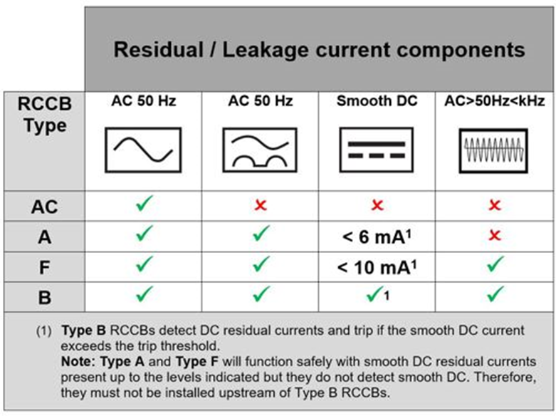
Type AC RCDs are affected by residual DC components and can become desensitized or ‘blinded’ and may not operate within the required time or, in some instances, may not operate at all. Table 1 summarizes the various types of RCD referred in BS 7671:2018+A2:2022 and their resilience to DC components.

Given the prevalence of electronic equipment in most installations, it is difficult to see how the electrical designer will be able to justify the use of Type AC RCDs. Many manufacturers have discontinued Type AC RCDs, preferring to supply type A as a minimum. Therefore, in future it is possible that Type AC RCDs will become obsolete due to lack of demand and Type A RCDs will become the common choice for most new installations, so it is important to understand the changes to the requirements for RCD testing.

See the chart below:
 

We can supply custom made power distribution boxes in many different configurations, these are available in rubber, thermoplastic, polypropylene, or steel frame.

We can also have cables made to order.

Please contact us to discuss your requirements and we will be more than happy to put together a quotation for you. 

We can deliver to anywhere in mainland UK and Islands using DPD or others. We also deliver further afield including to the EU, Australia, NZ, Middle East, Africa and the USA. We have FedEx and DHL accounts - anywhere is possible.

We use an established local courier company who can guarantee same day delivery throughtout the UK, subject to delivery charges. If your order is urgent and the products you require are in stock, we can arrange for same day delivery. 

Please note, this is also subject to availability and the time that the request is made; if the request comes too late in the day, it may not be possible to arrange for same day delivery. 

We don’t mind if you want to collect your order from us, we’ll try to be as flexible as possible. Please give us plenty of time to pick your order though, please also let us know prior to arriving.

We love to work on projects large or small however, we can often offer special pricing on the larger opportunities. Call us with your requirements - we would expect to be able offer you the most competitive of quotations.

Despite our best efforts there is occasionally a need for after-sales assistance. Rest assured that we will always provide prompt and helpful support for any problems you may encounter. Please contact us if you require any further information.

We have a direct relationship with our manufacturers, all based in the EU. This is your guarantee of a great product, sourced from a great company. Our mission; to bring you the very best products at the most competitive prices, from the very best companies in their chosen fields.